I had a few Texas Instruments BQ32000 real time clock chips lying around that I have been wanting to play with for ages. The only problem? They're in the SOIC-8 package type. Bummer. I want a nice easy DIP to push satisfyingly into my breadboard.
A quick search on eBay revealed that you can get pre-made boards that you solder your chip onto and hey-presto, you've got a DIP package. However, I was feeling impatient (after all, when will you be more conscious of the passing of time than when trying to get an RTC up and running?!) plus, for the price of the conversion board, I may as well just buy an RTC that's in the correct form factor and start using it as soon as the postman drops it off.
I had some stripboard and some header pins also lying around...Hmm, can anyone sense a soldering iron session coming on?
Step 1:
Take a picture of the stripboard and quickly sketch where the chip will go (on my Galaxy Note - such a handy phone), to make sure I don't get it wrong when I'm getting carried away with the craft knife in the next step. The red rectangle is the body of the chip, the white lines are the pins, the black lines are where I will need to cut and the blue are where I will need to solder new connections later.
Why, oh why, didn't I choose red for the cut lines and black for the chip outline, I hear you cry? I don't know why, but this is one of those moments that I'll regret for the rest of my life.
Step 2:
Make sure the chip lines up, then get a sharp knife and hack away.
Step 3:
Create little solder pads where the chip's feet will go (you might want to check that you have done your cutting correctly with a continuity tester)
Step 4:
Solder the chip on, create the 'jumper' connections between the outer strips and the outer legs of the pin and then solder on the header pins.
Does it look pretty? Hell no! But, does it get the job done? Hello no!
I got readings back from the chip, but the time never updated and when I checked the oscillator fail bit, it was set.
I forgot that the BQ32000 runs on 3.3V and I connected it to my 5V Arduino. I had intended to use a potential divider to step the voltage down (and hope that it worked at whatever the I2C frequency runs at on the Arduino), but in my excitement, I just connected it straight up.
I had also made such a mess of the soldering that I thought maybe I had overheated the chip.
I desoldered that chip and put another on. This time I tried to keep my soldering quick. To rule out the 5V/3.3V issue, I created an Arduino on a breadboard, running on 3.3V at 8MHz (using the internal oscillator). This was ridiculously easy to do. I'll try and write a post about it.
I could have used a logic-level shifter, but I didn't have one and they cost about as much as an RTC anyway and in any case, weren't you listening before? I want this RTC running, like, NOW!
 |
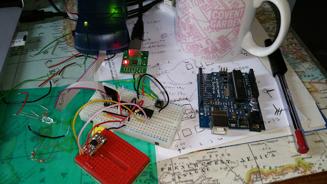
| Here is the second BQ32000 connected to an ATmega168 running on 3.3V (clocked at 8MHz) |
Second attempt? Same result. Either I'm not using the chip correctly (but I think I am - I checked that the run bit was set), or I keep frying them with my ham-fisted soldering. As I said previously, you can get RTCs including a battery online really cheaply, so at this point, I cut my losses and ordered one of those.
It's not all bad, though, because I like the sound of the DS3231 with its programmable alarms so I have abandoned the BQ32000. I'm thinking of using the DS3231's alarm feature to wake my Arduino out of a power down state on a sensor project I'm about to start. Plus, now I've got a ready-made SOIC-8 to DIP-8 converter for the next time I feel like destroying a chip.


No comments:
Post a Comment